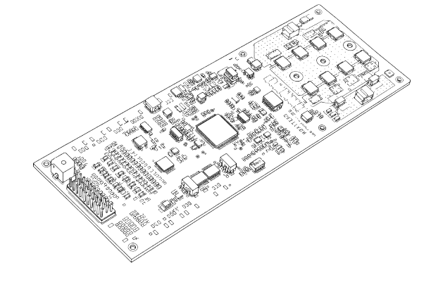
The BharatBMS 51.2V is a highly versatile BMS designed to power both ESS and EV applications from a single hardware platform. Instead of requiring separate board designs, the system is configured entirely through firmware, enabling faster development, lower production costs, and seamless customization. This unified architecture gives OEMs the flexibility to deploy the same BMS across multiple applications while maintaining high standards of safety, performance, and reliability.
Key Features
Supports up to 16 battery packs in parallel
51.2V nominal battery pack voltage
Up to 100A continuous and 150A peak current support
Advanced cell voltage monitoring and balancing
Hardware and software based safety protection
Two isolated CAN, RS-485, and UART communication interfaces
Configurable design for both ESS and EV applications
Here is a closer look at the architecture behind those specifications, covering the questions that come up most from engineers evaluating the board.
Which vehicles can use BharatBMS-ESS-51.2V?
The BharatBMS 51.2V is suitable for electric vehicles running on 48V and 51.2V battery systems, making it a versatile Lithium Battery BMS for Electric Vehicles. Common applications include:
BMS for E-Rickshaw
BMS for Electric Two Wheeler
BMS for Three Wheeler applications
BMS for Electric Cargo Vehicle
Golf carts, utility vehicles, and other low-speed electric mobility solutions
Its configurable architecture allows manufacturers to customize the BMS according to the vehicle's performance and safety requirements.
Does it protect against theft, especially for EVs?
Yes. There is a built-in gyroscope and motion sensor onboard. If the vehicle or battery is moved unexpectedly (say, someone is trying to steal it), the system can detect that motion and flag it. Since the whole board is configurable, this feature can be turned on or tuned specifically for EV customers who need it, while ESS customers who do not need it simply will not use it.
What is the cell monitoring range and how is balancing implemented?
Per-cell voltage monitoring covers 0V to 5V across up to 18 series cells. Balancing runs on-die on the monitoring front end rather than through a discrete external circuit, at 120mA on this configuration against a 300mA rated ceiling on the chip, leaving margin to raise the balancing rate for higher-capacity packs without a hardware revision. Open-wire detection resolves to the individual sense line, so a broken tap between pack and board reports as a specific cell fault rather than a generic monitoring error.
How is current actually measured on the board, and what role do the shunts play?
Current sensing runs through a dedicated INA (current sense amplifier) paired with two shunt resistors on the power path. The shunts sit in-line with the current flow, and the small voltage drop across each one is what the INA reads to derive the actual current value, rather than inferring it indirectly from voltage or timing. Using two shunts rather than one gives the measurement a cross-check, which matters at the higher end of the 100A continuous / 150A peak range where a single-shunt reading would be more exposed to drift or a single point of failure. This feeds the same fault-detection layer used for overcurrent and short-circuit protection, so current sensing is not just a telemetry number, it is part of the protection loop itself.
Separately, a load-side voltage sense circuit tracks the voltage on the load side independent of the battery-side measurement, which is what lets the board tell the difference between a battery-side fault and a load-side fault instead of reporting one generic voltage error.
What is running the safety and fault logic, and how much processing headroom does it have?
An automotive-grade MCU with enough onboard memory to run cell balancing, fault detection, and state estimation concurrently rather than sequentially. The board carries automotive functional safety certification, with redundancy split across two layers: firmware-level fault detection, and a parallel hardware layer for short circuit, overcurrent, and precharge fault conditions that trips independent of MCU execution state.
What makes the AFE on this board different from a typical external balancing setup?
The AFE (Analog Front End) has the balancing MOSFETs built directly onto the chip, so there is no separate balancing board or external switching circuitry needed to manage the 18 cells. That is a meaningful difference from designs where balancing is handled by a discrete circuit sitting alongside the monitoring IC, since it cuts down on board area, wiring, and an extra set of failure points.
The certification behind the AFE is what backs the redundancy story: the checks are not limited to what firmware catches after the fact. There are multiple internal redundancy paths running on the chip itself, in addition to the checks that can be implemented on the firmware side, so a fault gets caught by more than one layer before it becomes a problem. Open-wire detection, resolving down to the specific cell tap rather than a generic pack-level error, is one direct result of that internal redundancy.
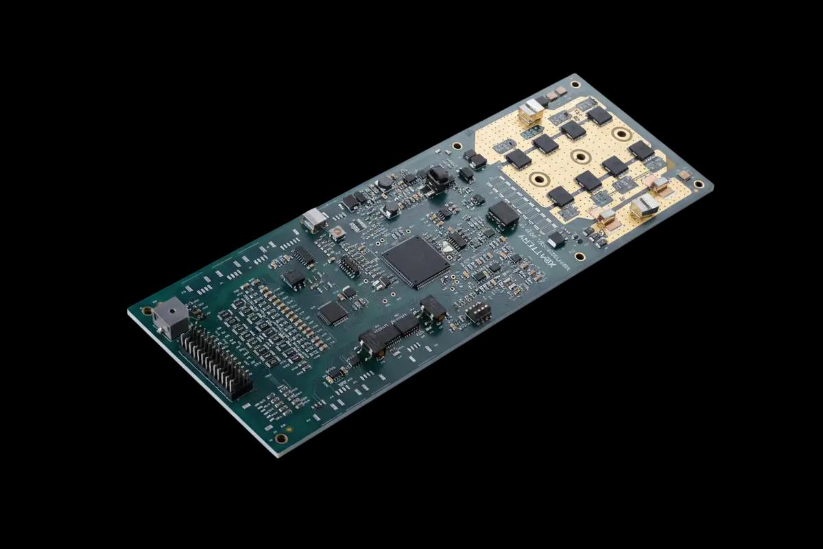
How is the power stage architected, and what is the current rating?
Eight MOSFETs, four high-side and four low-side, on a single shared path for both charge and discharge rather than dual independent paths. Rated for 100A continuous and 150A peak, with a heat sink mount on the underside for sustained operation at the upper end of that range. A precharge stage limits inrush current on initial load connection, and current is measured continuously through a shunt-based sense circuit feeding the analog front end.
Can it talk to other devices like an inverter or a vehicle controller?
Yes, and this is one of its stronger points. It comes with:
Two independent CAN connections (a common industrial communication protocol), both electrically isolated for safety
Two serial ports, one for a configuration tool, one to talk to an inverter
Support for RS-485, another common industrial communication standard
For EVs specifically, it can also receive ignition and control signals over CAN from the vehicle's main controller so turning the vehicle on or off can be managed digitally, making it a solid fit for any Battery Management System for EVs that needs tight integration with the vehicle's electronics.
What is on the back of the board?
CAN transceiver, balancing resistor bank, EEPROM for configuration and fault log persistence, and an RTC (Real-Time Clock) with a dedicated backup battery so timekeeping survives a full pack disconnect. A DIP switch handles address assignment for parallel operation. An onboard buzzer provides local audible fault indication independent of any connected display or host system.
Can more than one of these boards work together?
Yes. If you are building a larger battery bank using multiple packs in parallel, the DIP switch on the back of the board lets you assign each unit its own address, like giving each battery a name tag so the system knows who is who, supporting up to 16 units on a shared bus.
How do you configure or set it up?
Configuration runs through the same dedicated tool over a serial port, with three levels of access. An OEM (the company actually building the final product) gets full access to every setting, while other customer tiers get a more limited, safer set of options.
Frequently Asked Questions:
What differentiates this from a basic protection-only BMS? On-die active balancing, a hardware fault layer that runs independent of firmware execution, and an MCU with enough headroom to run health estimation alongside real-time protection, combined on one board rather than distributed across add-on modules.
Is the hardware identical across ESS and EV deployments? Yes. The board is a single hardware revision; ESS and EV behavior is set entirely through firmware configuration, including which peripherals (gyroscope, CAN ignition control) are active.
What is the cell chemistry compatibility? Calibrated for lithium chemistries (LFP, NMC) at a 0V to 5V per-cell monitoring range, consistent with 51.2V nominal pack configurations.
What constitutes the hardware safety layer specifically? Dedicated analog circuitry for short circuit, overcurrent, and precharge-related fault detection, operating independently of MCU state, in addition to firmware-level protection and gyroscope-based motion detection for EV applications.
What is the maximum parallel bank size supported? Up to 16 units, addressed individually through the onboard DIP switch.


